JK flip-flop
JK Flip-Flop
This is a configurable component with changeable CLOCK edge triggering(POSITIVE and NEGATIVE), changeable level triggering (active LOW or HIGH) for Set and Reset inputs and complementary outputs. The Clock, Set and Reset signals polarity determines four types of functionality and four individual types of Flip-Flops, respectively:
- Positive Clock signal, active HIGH asynchronous Set and Reset inputs
- Positive Clock signal, active LOW asynchronous Set and Reset inputs
- Negative Clock signal, active HIGH asynchronous Set and Reset inputs
- Negative Clock signal, active LOW asynchronous Set and Reset inputs
Any type of the above described flip-flops can be configured using two checkboxes: one for CLOCK signal, one for both Set and Reset signals.
1. Positive Clock, Active HIGH Set and Reset inputs type
This type of JK Flip-Flop will function on the rising edge of the Clock signal. The J and K inputs must be stable prior to the LOW-to-HIGH clock transition for predictable operation. The set and reset are asynchronous active HIGH inputs. When high, they override the clock and data inputs forcing the outputs to the steady state levels.
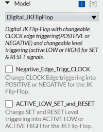
In order to select this type of Flip-Flop, both checkboxes for CLOCK and SET/RESET need to be left empty(see the screenshot below).
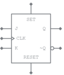
The symbol for this type of JK Flip-Flop is the one below:
Function table for POSITIVE CLOCK, active HIGH Set and Reset
| Inputs | Outputs | |||||
|---|---|---|---|---|---|---|
| SET | RESET | CLK | J | K | Q | ~Q |
| L |
H |
X | X | X |
L |
H |
| H |
L |
X | X | X | H |
L |
| H |
H |
X | X | X | NS |
NS |
| L |
L |
↑ | L |
L |
NO CHANGE |
|
| L |
L |
↑ | L |
H |
L |
H |
| L |
L |
↑ | H |
L |
H |
L |
| L |
L |
↑ | H |
H |
TOGGLE |
|
H = HIGH Level
L = LOW Level
X = Don't Care
↑ = LOW-to-HIGH Clock transition
NS = Not Stable state of the outputs when both SET and RESET inputs are HIGH
SET, RESET = Asynchronous Inputs
2. Positive Clock, Active LOW Set and Reset inputs type
This type of JK Flip-Flop will function on the rising edge of the Clock signal. The J and K inputs must be stable prior to the LOW-to-HIGH clock transition for predictable operation. The set and reset are asynchronous active LOW inputs. When low, they override the clock and data inputs forcing the outputs to the steady state levels.
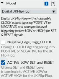
In order to select this type of Flip-Flop, the checkbox for CLOCK is left empty while the checkbox for SET/RESET needs to be checked (see the screenshot below).
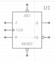
The symbol for this type of JK Flip-Flop is the one below:
Function table for POSITIVE CLOCK, active LOW Set and Reset
| Inputs | Outputs | |||||
|---|---|---|---|---|---|---|
| SET | RESET | CLK | J | K | Q | ~Q |
| H |
L |
X | X | X |
L |
H |
| L |
H |
X | X | X | H |
L |
| L |
L |
X | X | X | NS |
NS |
| H |
H |
↑ | L |
L |
NO CHANGE |
|
| H |
H |
↑ | L |
H |
L |
H |
| H |
H |
↑ | H |
L |
H |
L |
| H |
H |
↑ | H |
H |
TOGGLE |
|
H = HIGH Level
L = LOW Level
X = Don't Care
↑ = LOW-to-HIGH Clock transition
NS = Not Stable state of the outputs when both SET and RESET inputs are LOW
SET, RESET = Asynchronous Inputs
3. Negative Clock, Active HIGH Set and Reset inputs type
This type of JK Flip-Flop will function on the falling edge of the Clock signal. The J and K inputs must be stable prior to the HIGH-to-LOW clock transition for predictable operation. The set and reset are asynchronous active HIGH inputs. When high, they override the clock and data inputs forcing the outputs to the steady state levels.
In order to select this type of JK Flip-Flop, select the checkbox for CLOCK while the one for SET/RESET is left empty (see the screenshot below).
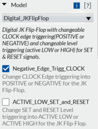
The symbol for this type of JK Flip-Flop is the one below:
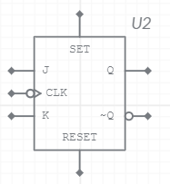
Function table for NEGATIVE CLOCK, active HIGH Set and Reset
| Inputs | Outputs | |||||
|---|---|---|---|---|---|---|
| SET | RESET | CLK | J | K | Q | ~Q |
| L |
H |
X | X | X |
L |
H |
| H |
L |
X | X | X | H |
L |
| H |
H |
X | X | X | NS |
NS |
| L |
L |
↓ | L |
L |
NO CHANGE |
|
| L |
L |
↓ | L |
H |
L |
H |
| L |
L |
↓ | H |
L |
H |
L |
| L |
L |
↓ | H |
H |
TOGGLE |
|
H = HIGH Level
L = LOW Level
X = Don't Care
↓ = HIGH-to-LOW Clock transition
NS = Not Stable state of the outputs when both SET and RESET inputs are HIGH
SET, RESET = Asynchronous Inputs
4. Negative Clock, Active LOW Set and Reset inputs type
This type of JK Flip-Flop will function on the falling edge of the Clock signal. The J and K inputs must be stable prior to the HIGH-to-LOW clock transition for predictable operation. The set and reset are asynchronous active LOW inputs. When low, they override the clock and data inputs forcing the outputs to the steady state levels.
In order to select this type of JK Flip-Flop, select both the checkboxes for CLOCK and for SET/RESET (see the screenshot below).
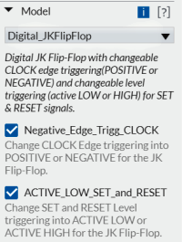
The symbol for this type of JK Flip-Flop is the one below:
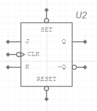
Function table for NEGATIVE CLOCK, active LOW Set and Reset
| Inputs | Outputs | |||||
|---|---|---|---|---|---|---|
| SET | RESET | CLK | J | K | Q | ~Q |
| H |
L |
X | X | X |
L |
H |
| L |
H |
X | X | X | H |
L |
| L |
L |
X | X | X | NS |
NS |
| H |
H |
↓ | L |
L |
NO CHANGE |
|
| H |
H |
↓ | L |
H |
L |
H |
| H |
H |
↓ | H |
L |
H |
L |
| H |
H |
↓ | H |
H |
TOGGLE |
|
H = HIGH Level
L = LOW Level
X = Don't Care
↓ = HIGH-to-LOW Clock transition
NS = Not Stable state of the outputs when both SET and RESET inputs are LOW
SET, RESET = Asynchronous Inputs