Your browser is incompatible with Multisim Live. Use the Chrome™ browser to best experience Multisim Live.
SCR switch
This device is a simplified SCR (silicon-controlled rectifier) thyristor.
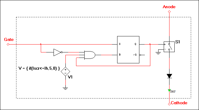
Its model is represented by the following:

When the gate voltage (relative to ground) is higher than the Trigger gate voltage (Vth), a digital high is seen by the inverter and the SR-latch. This sets the latch, which turns on switch S1, and allows current to flow through the SCR if the diode is forward biased. When the gate voltage drops below the Trigger gate voltage, the latch remains set if the SCR current is greater than the Holding current (IH).
The only path where current can flow within the entire model is through switch S1 and the diode.
No current flows anywhere else in the model including through the gate. The gate is designed to act more as an ideal control port than an electrical port with impedance. This SCR model is intended for system-level simulation where the importance of an SCR's basic triggering behavior dominates all other behavior.
- 555 timer
- 7-segment display
- ABM sources
- AND
- Angle wrap
- Arbitrary sources
- BCD to 7-segment decoders
- Binary Counters
- BJTs
- Brushless DC machine
- Brushless DC machine hall
- Capacitor
- Combination relay
- Configurable transformer
- Creating custom component models
- Current controlled SPST
- D flip-flop
- D latch
- DC machine permanent magnet
- DC machine wound field
- DC voltage/current sources
- Decoders/Demultiplexers
- Delay
- Digital buffer
- Digital clock
- Digital constant
- Diode
- Diode switch
- Divider
- Full Adders
- GaAsFETs
- GTO switch
- Ideal comparator
- Impedance block
- Incremental encoder
- Induction machine squirrel cage
- Induction machine squirrel cage (E)
- Induction machine wound
- Induction machine wound (E)
- Inductor
- Inductor coupling
- Inertial load
- Inverter
- JFETs
- JK flip-flop
- LM555CN - Highly Stable 555 Timer
- Lossy transmission line
- Machine modeling
- MOSFETs
- Multiplier
- NAND
- NOR
- Opamps
- OR
- Phase angle controller
- Phase angle controller 2 pulse
- Phase angle controller 6 pulse
- Potentiometer
- Probes
- Pulse width modulation (PWM) components
- PWM sinusoidal 3 phase
- Relays
- Resistor
- Resolver
- SCR switch
- SPDT switch
- SPST double break
- SPST switch
- SR flip-flop
- SR latch
- Stepper 2 phase
- Stepper 2 phase 2 winding
- Synchronous permanent magnet
- Synchronous permanent magnet E
- Synchronous permanent magnet hall
- T flip-flop
- Three phase delta
- Three phase wye
- Transistor switch
- TRIAC switch
- Voltage controlled SPDT/DPDT
- Voltage controlled SPST
- Voltage differentiator
- Voltage gain block
- Voltage integrator
- Voltage summer
- XNOR
- XOR
- Zener